 |
 |
 |
Multi_R_Designer
Tutorial |
 |
 |
 |
aa
Creation of a frame for the
user's file:
The creation of a frame in which proprietary data
will be stored, minimizes hardy manipulation during the simulation process.
The frame is specific to the property (or properties) to be simulated and
the selected models.
In this case, the frictional pressure drop in
a trickle bed reactor ( )
is the property to be simulated. Inputs are obtained from MultiRDesigner/sample/sample.csv
(user's file) and the file with the specific frame created in this example
is user1.csv.
The procedure consists of the following steps:
STEP 1:
-
Select Simulation/Start new simulation from
the bar menu or press
 .
.
-
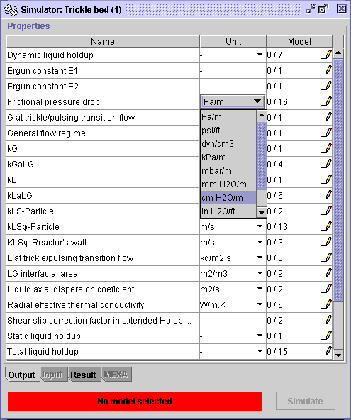
A Simulator: Trickle bed dialog window is opened. Go to Frictional
pressure drop, choose the desired unit
 in the
Unit field. At the bottom of the dialog window, a warning
indicates that no model is selected. In the Model field, 0/16
means that none of the 16 available models are selected.
STEP 2:
In the Model field, select the pencil  .
Models available to predict
  are
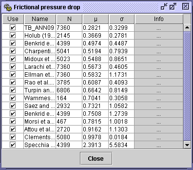
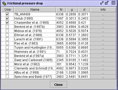
depicted in a Frictional pressure drop dialog window. All available
models can be selected by pressing the Use heading, or specific
models can be accessed with the check boxes.a
In this example all models are considered. TB_ANN09 is the artificial
neural network correlation developed at Laval University. The  and
and fields
depict for each model the Average
Absolute Relative Error (AARE)
and
standard
deviation on absolute relative error calculations, respectively,
based on the whole Multi_R_Designer integrated databank.
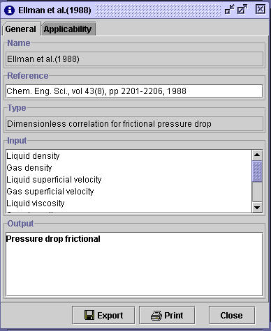
Informations about a model/correlation could be found by pressing the
Info
filed. In General panel, for Ellman et al.(1988) (example below),
are depicted the Reference of the model, its Type (empirical
correlation using dimensionless inputs), list of the model's
Inputs
in dimensional form (liquid density, gas density ...), and the Output
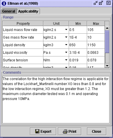
in dimensional form also. In Applicability panel,
a domain
of validity for each model input is given in the unit of your choice. The
range of validity is also indicated on the graphical representation of
the simulated variable by open symbols. Some pertinent Comments
on the formulation of the model are also presented.
STEP 3:
-
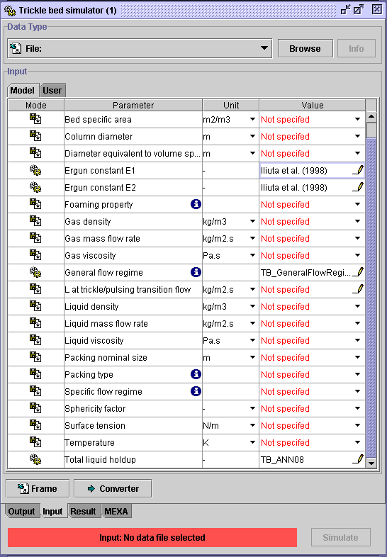
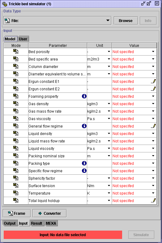
In the Input tab of the Simulator: Trickle bed
dialog window,
the inputs required for the application of the selected models (STEP
2) are given.
-
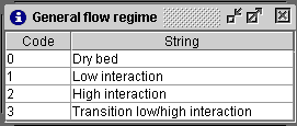
Some inputs necessitate codes. To know them, press(
 )
)
| Foaming property

|
General flow regime
|
-
The presence of a pencil
 in the Column index in file field means that the corresponding input
can be simulated (corresponds to
 in
the Summary models' input table)
For example :
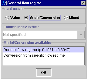
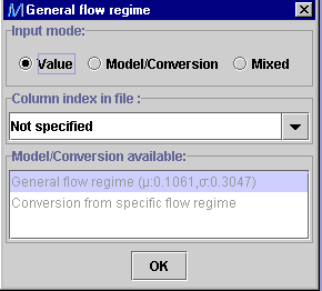
a) if the general flow regime is available in the user's file(as
a code), choose Value option.
b) if not available in the user's file, choose the Model/Conversion
option.
To select the desired model, click on its name (the performance of the
model, in terms of  and
and ,
on the Multi_R_Designer databank is given in parethesis).
When the specific flow regime is available in the user's file,
Conversion
from specific (to general) flow regime is a routine which converts
the code of a specific flow regime to the general flow regime code (see
Coded
variables).
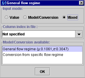
c) The Mixed option can be selected if the model input,
general flow regime in this case, is known only for a portion of the database
while the remaining are still unknown. It enables the user to determine
the experimentally unknown general flow regime with a specified model.
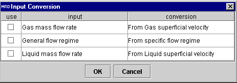
As it is shown in the inputs table, Gas and Liquid mass flow
rate are used instead of superficial velocities. If in the user's file,
the superficial velocities are used, a converter to superficial
velocities is available. Select what to be converted and press OX
STEP 4:
-
In this example, Ergun constants, General flow regime and
Total
liquid holdup are not available in sample.csv (the user's file).
They are estimated by the TB_ANN correlations. Therefore, they do not appear
in the frame of the file to be used for simulation.
-
If an input is not available, the corresponding model output will not be
simulated. In this example, specific flow regime is not available in
sample.csv.
Thereofore, frictional pressure drop will not be computed for models involving
the specific flow regime as an input.
-
 means
that the input is available in the user's file,
  means that it will be estimated using a model.
STEP 5:
-
All inputs will appear in the frame of the user's file. If you want other
variables to appear, such as experimental frictional pressure drop, click
on the
User tab at the top of the Input
box.
-
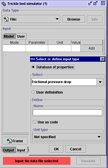
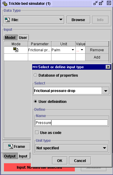
Click on Add. The Add user input dialog window appears.
-
The output to be simulated appears in the Select box. This, if the
experimental data is available to carry out comparison with the simulated
one. If not, click on User definiton option, and identify
specifically the desired variable in the
Name box. It can be used
as a code (select the check box). Define its unit. Not specify means
that it is in SI.
-
Press OK. The identified variables will appear in the Parameter
column and saved in the frame.
-
Do not forget to assign the unit, if necessary.
STEP 6:
-
Press Frame and choose the name and location of the spreadsheet
in .csv format. In this example, user1.csv is assigned.
STEP 7:
-
Open user1.csv from any data processing software and fill the columns
with the data to be simulated (from sample.csv). Do not forget to
give to the coded inputs their corresponding number. Save the file (same
name and format). Now the user's file: user1.csv is ready to be
used for manual simulation.
 |
 |
 |
Multi_R_Designer
Tutorial |
 |
 |
 |
![]() )
is the property to be simulated. Inputs are obtained from MultiRDesigner/sample/sample.csv
(user's file) and the file with the specific frame created in this example
is user1.csv.
)
is the property to be simulated. Inputs are obtained from MultiRDesigner/sample/sample.csv
(user's file) and the file with the specific frame created in this example
is user1.csv.
![]() and
and![]() ,
on the Multi_R_Designer databank is given in parethesis).
,
on the Multi_R_Designer databank is given in parethesis).
