 |
 |
 |
Multi_R_Designer
Tutorial |
 |
 |
 |
aa
Sub-problem 3.1:
Total liquid hold-up and flow regime for air-kerosene downflow at 1 atm
(Ni/Mo/Al2O3 spheres; G = 0.2 kg/m2s;
L = 10 kg/m2s)
1) Start a new project by
selecting Start new query  .
.
2) Apply the following problem
specifications, namely the Liquid composition: 100% kerosene, Gas
composition: 100% air, Pressure: 1 atm, Packing type:
spheres, Packing material: Catalyst (Ni/Mo/Al 2O3)
and Liquid hold-up measurement technique: Weighting.
-
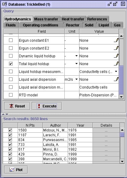
First, select the Hydrodynamics
tab and check the box corresponding to Total liquid holdup, then
Execute.
It will extract 8650 data sets containing a total liquid hold-up
value.
-
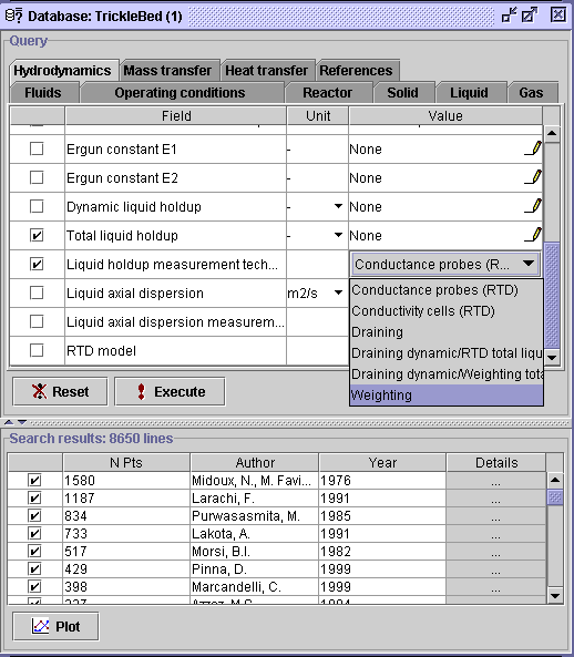
In the same tab, check the box related
to Liquid holdup measurement technique and select the corresponding
Value
field combo box
 .
A choice is given to the user. In this case, it comprehends liquid holdup
measurement techniques going from Conductance probes (RTD)
to
Weighting
procedures. Select the latter choice (Weighting) and press
Execute.
A total of 3310 liquid holdup measurements were obtained via a Weighting
procedure.
 |
 |
-
In the Fluids tab, select the
Add
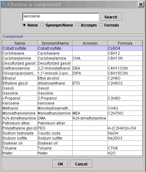
button in the Liquid phase section. Write kerosene in the
Search
box and activate the Search button. It will extract all components
that contain this string. The exact component name will usually give the
user one selection if it is available in the list. Press OK.
-
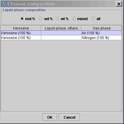
Select (unspecified)
 in the Liquid phase composition field. The following dialog window
will appear. Highlight Kerosene (100%) associated with a gas composition
of Air (100%) and press OK, then Execute. The data
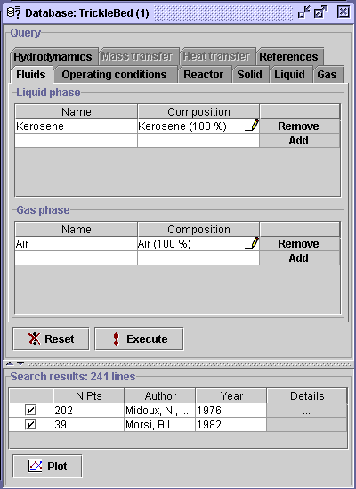
number is reduced to 241 from Midoux et al. and Morsi.
 |
 |
-
Select the Operating conditions
tab. Check the box corresponding the Pressure field. Change the
unit from Pascals (Pa) to atmospheres (atm).
-
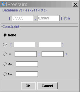
Select the corresponding pen
 in the Value field. It gives the min-max range for the 241
measurements, which were carried out at more or less 1 atm. Therefore,
pressure specifications becomes trivial. Do not enter any values, and check
the none option, then OK. The user may also deselect the
Pressure
field (optional).
-
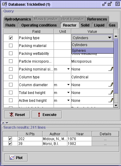
Select the Reactor tab and check
the Packing type option. In the Value field
 ,
two packing types are presented to the user. Choose Spheres, then
Execute.
-
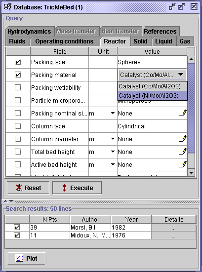
Check the Packing material box
and choose Catalyst (Ni/Mo/Al2O3), then Execute. A total
of 39 data sets from Morsi (1982) allow all the specifications
established in this case problem to be fulfilled.
3) Save  the project as Case problem III.mr.
aa
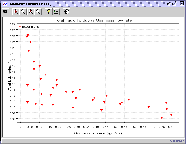
4) Select the Plot
button  .
.
aa
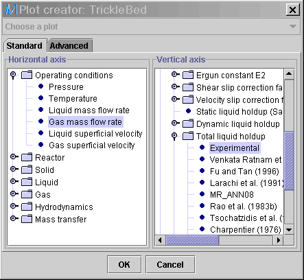
5) Specify the X-axis as
gas mass flow rate (In the Horizontal axis panel, click on the Operating
conditions knob, and highlight Gas mass flow rate).
aa
6) Specify the Y-axis astotal
liquid holdup (In the Vertical axis panel, click on the
Hydrodynamics
knob,
then on Total liquid holdup knob, and highlight Experimental).
aa
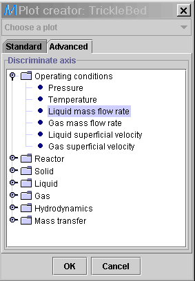
7) In the Advanced
tab, specify the discriminate value as liquid mass flow rate (Click on
the Operating conditions knob, and highlight Liquid mass flow
rate). Press
OK.
8) Select the Discriminate
series button.
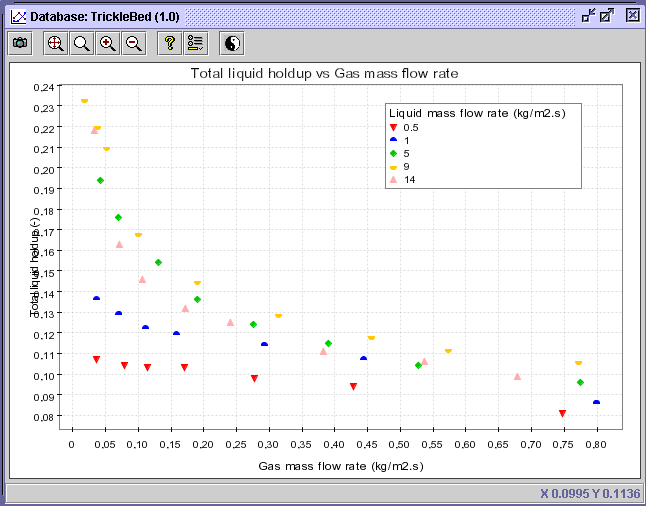
9) In the Value discrimination
panel, the min-max range for the liquid mass flow rate rests between 0.5
and 14 kg/m2s. Divide it into an infinite number of classes
(i.e. 1000), and press OK. A new diagram with specific series
in terms of liquid mass flow rate will be created.
10) Five distinctive liquid
mass flow rates are exposed in the legend. The problem statement requests
the evaluation of total liquid holdup at a liquid mass flow rate of 10
kg/m2s, which is located between the 9 and 14
kg/m2s series showcased on the diagram. To alleviate the
diagram, unselect the series corresponding to liquid mass flow rates of
0.5,
1
and 5 kg/m2s. Right click on the legend and uncheck the
boxes related to these series in the Draw field. Press
OK.
CONCLUSION #1: Based on the latter diagram, it
can be concluded that the total liquid holdup for air-kerosene downflow
through a bed of spherical Ni/Mo/Al2O3 catalysts
at air mass flow rate of ca. 0.2 kg/m2s and kerosene
mass flow rate of 10 kg/m2s should rest near 0.14
or
14%
of kerosene volume per bed volume.
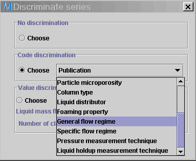
11) Select the Discriminate
series button  .
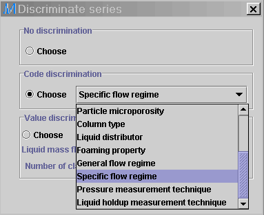
Change the Value discrimination option for Code discrimination
option, and choose General flow regime in the combo box
 .
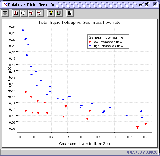
Press OK. The same diagram with a new discrimination will be created.
CONCLUSION #2: By comparing the last two diagrams,
it should be expected that the high interaction flow regime will pre-dominate
based on the operating conditions established in the problem statement
and experimental results given by Morsi.
12) For more precise information
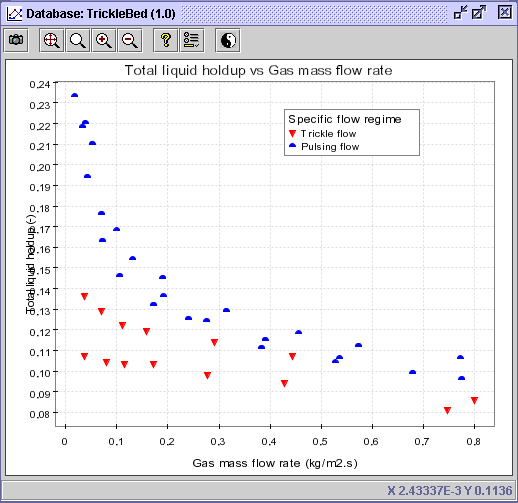
on the flow regime, select, in the Discriminate series  (Code discrimination), the Specific flow regime option. Press
OK.
CONCLUSION #3: The exact flow regime operation in the
high interaction region is the pulsing flow.
 |
 |
 |
Multi_R_Designer
Tutorial |
 |
 |
 |
![]() .
.


![]() the project as Case problem III.mr.
the project as Case problem III.mr.
![]() .
.
![]() button.
button.
.gif)
.gif)
![]() .
Change the Value discrimination option for Code discrimination
option, and choose General flow regime in the combo box
.
Change the Value discrimination option for Code discrimination
option, and choose General flow regime in the combo box![]() .
Press OK. The same diagram with a new discrimination will be created.
.
Press OK. The same diagram with a new discrimination will be created.
![]() (Code discrimination), the Specific flow regime option. Press
OK.
(Code discrimination), the Specific flow regime option. Press
OK.
